logic-circuits computer-architecture
Definition
Arithmetic Logic Unit
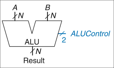
Control
The ALU takes two inputs and together with a control signal that selects the operation.
| Control signal | Function |
|---|---|
| Addition | |
| Subtraction | |
| AND | |
| OR |
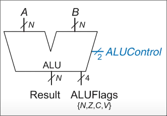
Flags
An ALU can also output status flags that summarise properties of the result.
| Flag | Meaning |
|---|---|
| the result is negative | |
| the result is zero | |
| the adder produces a carry out | |
| signed overflow occurs |
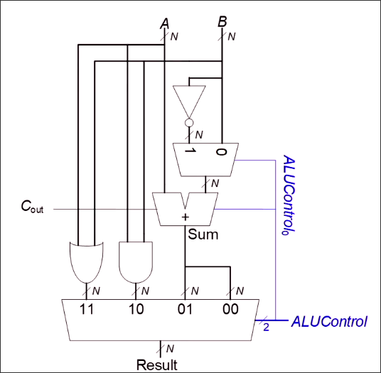
Implementation
One adder for addition and subtraction
A common implementation reuses one full adder for both addition and subtraction.
The key identity is:
So the circuit can:
- pass unchanged for addition;
- pass for subtraction;
- use the control bit as the carry-in.
This lets one adder implement both operations.
Adding status flags
The ALU can be extended so that it outputs the flags together with the main result.
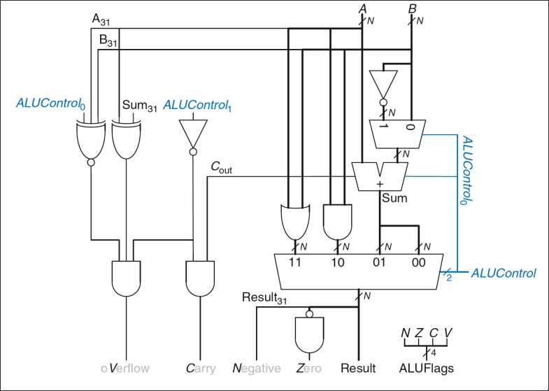
Overflow logic
The overflow flag is the most subtle part.
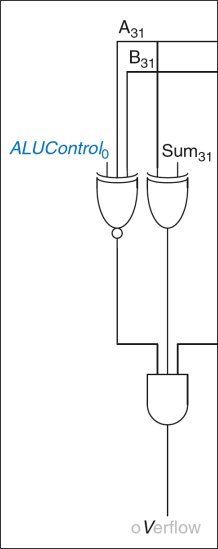
The logic can be read step by step.
-
The right-most gate enables the overflow logic only for addition and subtraction.

-
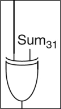
The middle gate checks whether the sign bit of the result differs from the sign bit of .
-
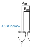
The left XNOR gate captures the sign pattern that can overflow:
- for addition, overflow is possible only when and have the same sign;
- for subtraction, overflow is possible only when and have different signs.
Putting these conditions together yields the signed overflow flag .