Definition
Single-Cycle Processor (RISC-V)
A single-cycle processor for RISC-V is a microarchitecture in which every instruction completes in one clock cycle.
This gives a CPI of , but the clock period must be long enough for the slowest instruction.
Performance
Program Excution Time
Examples
Example
We want to construct a single-cycle processor for the RISC-V instructions:
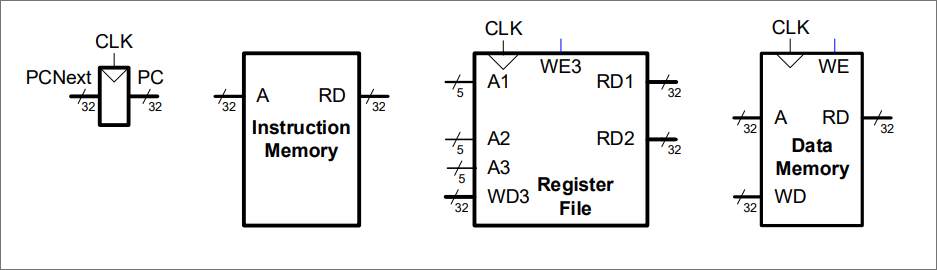
We need to represent three state components
We use four base components (special counter, read-only memory, read-write memories):
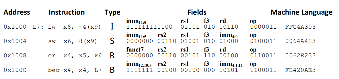
Consider the following examples program:
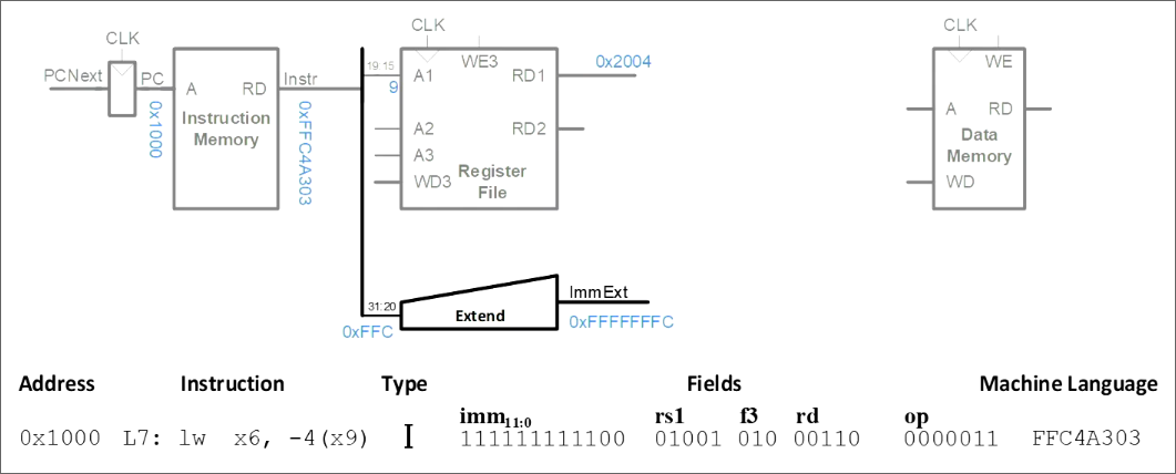
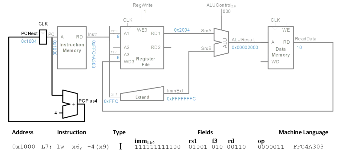
We start with the lw instruction. An lw instruction is an I-type instruction and thus formatted as follows:
Synopsis
I-type instructions use one source register (
rs1) and a 12-bit immediate (imm_{11:0}).The remaining fields provide the operation encoding:
Link to original
funct3selects the specific operation.rdnames the destination register.opidentifies the instruction as an I-type instruction.The lw instruction is located at address 0x1000. To fetch the instruction, we link the counter to the read-only memory to output the instruction (in bytes; one word):
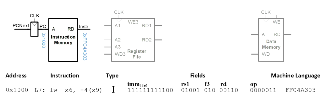
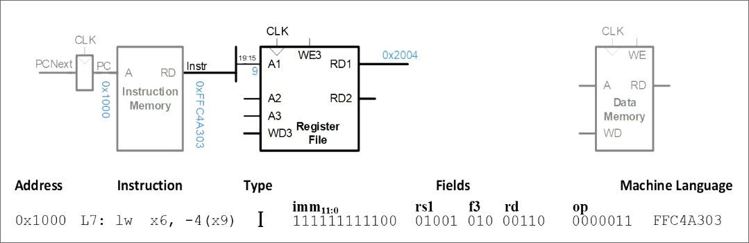
Next, we need to load the rs1 operand, which is x9 in our case. For I-type instructions, the rs1 value can be found at 19:15 in machine code. Hence, we connect the instruction to the A1 port of the register file:
Next, we need to sign-extend the immediate value -4, which is stored at 31:20:
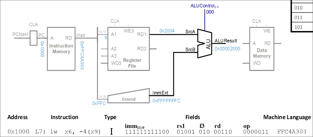
Now, we want to compute , i.e.:
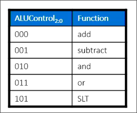
with ALU table:
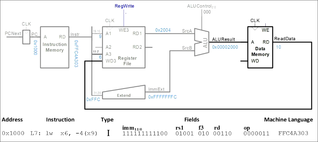
The ALUResult is now the actual memory address of the word we want to load, which we pass as A to the data memory block. The read data is then passed to the register file, which stores it:
Note that A3 contains 11:7, i.e. rd, the non-sign-extended register x9, and we have to signal the register file that it should write (external signal).
Finally, we have to load the next instruction. We now that one instruction is equal to , therefore, we add , i.e.:
We’ve now implemented the lw successfully in hardware.
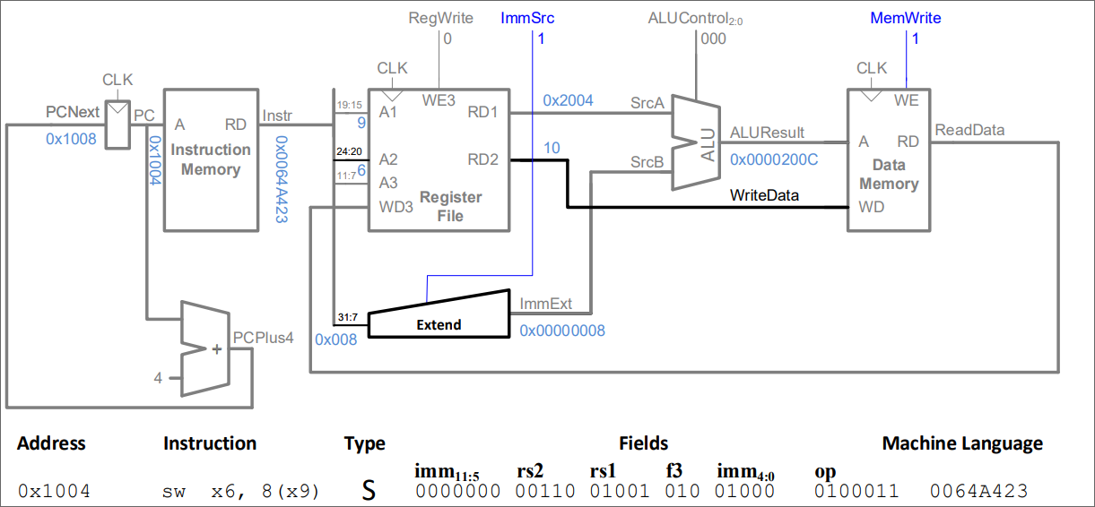
Next instruction: sw. The sw instruction is of type S, i.e. has the format:
Synopsis
S-type instructions use one source register (
rs2) and a split immediate offset (imm$_{11:5}$andimm$_{4:0}$).The remaining fields provide the operation encoding:
Link to original
rs1names the base register.funct3selects the specific store operation.opidentifies the instruction as an S-type instruction.The difference between I-type (lw) and S-type (lw) is the following:
To realise this, we’re doing the following:
- We pass 24:20, i.e. the target register rs2, to A3 (register file)
- We connect RD2 (the register file) to WD (data memory)
- We introduce control signals ImmSrc (whether S/T) and MemWrite.
We’re now able to process sw instructions.
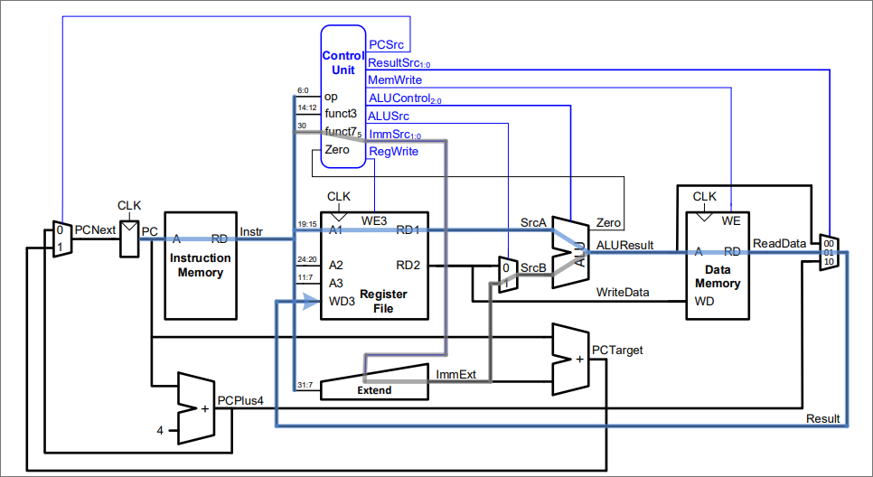
Single-Cycle Control:
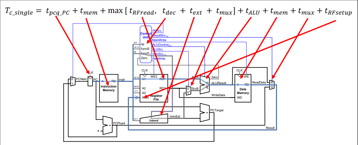
op Instr. RegWrite ImmSrc ALUSrc MemWrite ResultSrc Branch ALUOp 3lw 10010100035sw 00111X00051R-type 1XX00001099beq 01000X101Critical path: The blue path highlights the critical path. We can assume that is limited by critical path (lw).
The single cycle critical path is: